Super Easy to Use 3D Engine (Su3De) – Binary File Format Part 5 – Textures

Peanut Butter Jelly Time

OK…its time for textures.  We have everything we need for a textured 3D model in the .SU3 format except for textures – yes…we will have to add color maps for models that don’t have textures…but all in due time.  Right now…textures.

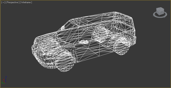
So, lets say we have a 3D model with geometry:

Ford Flex Model Geometry

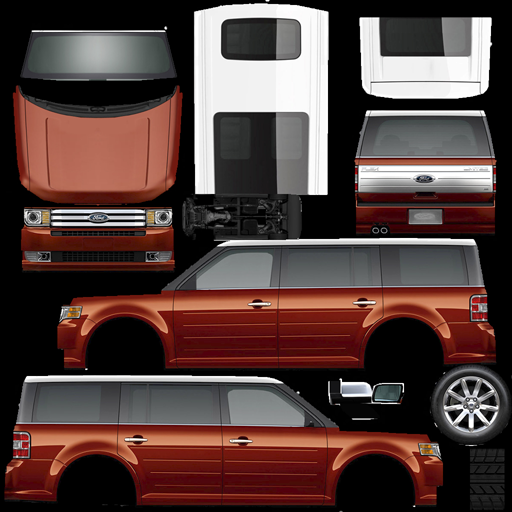
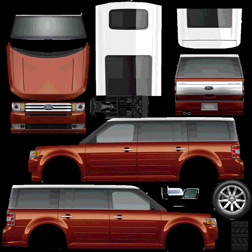
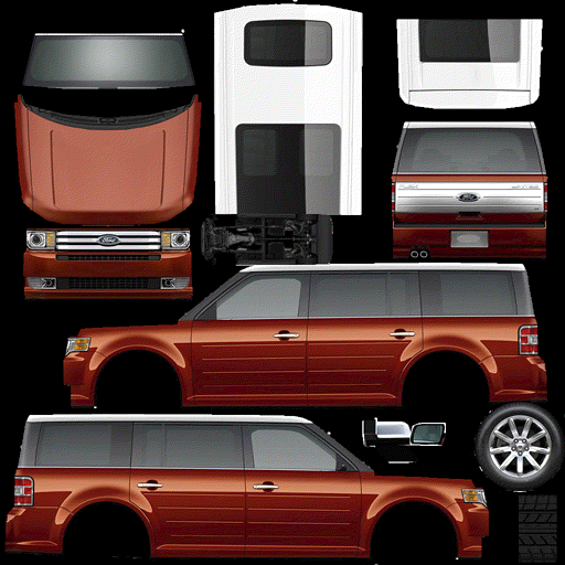
Now we want to add a texture map to it.

Ford Flex Model Texture

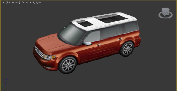
If all comes out right, we should get this when we render the model:

Ford Flex Model Rendered

A not so long winded texture discussion – hopefully

A texture is simply a bitmap. That’s it.  In the end, just a collection of pixels.  Usually the width and height of the bitmap (almost always) is a power of 2 – like 64×64, 128×128, 512×512, 512×128, etc.   The Ford Flex model texture is 512×512.  As you probably already know, the size of the texture is relatively unimportant – the larger the texture the more detail you can pack into it.  The problem is, the larger the texture, the more work the 3D renderer has to do to draw the model.  There is always a trade off between texture size and speed / performance.

So, what format can a texture be in?  THAT can end up being a complex question. Ultimately, the texture will end up in the format of the actual frame buffer of the graphics controller – but it will undergo a lot of changes along the way – getting sliced, diced, stretched, pulled, pushed, wrapped and mapped onto the triangles that make us the 3D model.  So, does it really matter what format the texture is in to start with? Well…actually yes…it does.  You see, the texture has to be pushed across the “host” memory interface into graphics memory prior to it getting used by the 3D renderer, so…in this case, while a bigger texture map gives you better visual results, smaller textures move across the host interface faster – again…a trade off.

Now…the first and obvious question that comes to mind is this…why can’t I just use PNG and JPG images for my texture map?  Well…you can…and…you can’t.  How’s that for an answer?

When you create your textures using whatever tool you use – PhotoShop, Z-Brush…whatever, you will most likely save out your texture as a pretty common format – like a JPG or PNG. You might even save out as a GIF (why…I don’t know…but you might). Most 3D engines, however, are going to require that you convert from one of these common formats into something it can actually understand and use.  SOME 3D engines will directly perform the JPG / PNG / GIF / blah blah conversion for you…but Su3De won’t.

Never fear, however, the Su3De .SU3 3D model conversion utility, however, will be DELIGHTED to do the texture conversion for you…

Now, the next question is – What will the SU3 model conversion utility convert the texture into?  Tongue in cheek answer – does it matter…do you really care?  Oh…you do? Well here is the answer then.

Bitmaps 101 – kind of

There are many different ways to express pixels in a bitmap.  Too many in fact.  For the purposes of further discussion R = Red component, G = Green component, B = Blue component and A = Alpha component.  As you are almost certainly aware, Alpha is the amount of transparency of the pixel with 0 being completely transparent and “maximum value” (whatever that is based on the bit depth) as fully opaque.

The lowest hanging fruit and simplest of the bitmap formats would be a straight 32-bit ARGB value.  This would mean that there would be 8 bits for each color component as well as the alpha component.  This ostensibly yields 4 billion possible color variations – again…kind of…but not really.  In reality, the number of possible color variations will be dictated by your LCD screen – or display device.  In many cases, the LCD panels are 18-bit yielding only 262,144 possible colors.  Most of the latest LCD panels are 24-bit wide which yields around 16.8 million possible colors. Simply food for thought when picking color depths for textures.

So…lets look at a 32-bit color depth texture:

32 bit frame buffer example

This is an example of “direct color”.  In this example, each pixel requires 4 bytes to represent the color information.  So, for our 16×8 texture, the requirement is 512 bytes.  Seems like a lot of memory for such a small bitmap, doesn’t it?  Now consider a texture that is 512×512 pixels. At 32 bit color, the memory requirement is a whopping 1MB – just for a single texture…like the Ford Flex texture above.  Is there a better way?  I daresay…there is.

What if we used LESS memory for each pixel…I mean do we REALLY need 8 bits for each component?  What if we cut the color depth in half?  Like use 16-bits per pixel instead?  Is this workable?  In fact, yes…it is.  Many / most of the 3D engines we work with will accept wither 32-bit or 16-bit color.  The trade-off?  The number of colors start becoming seriously limited.  Let me explain / show.

With 32-bit color, we have 8 bits for Red, 8 bits for Green and 8-bits for Blue and 8-bits for Alpha.  That means we have 256 SHADES of Red, 256 SHADES of Blue and 256 SHADES of Green to work with.  In many images, there are subtle color gradients that aren’t immediately obvious, because they blend together when we see them.  Our brain does that nifty little trick for us…  When we reduce the color depth, we reduce the number of “SHADES” of a particular color and this can create nasty artifacts called “banding” that makes images look…well…not so hot. Before we continue, lets talk about a couple of other color depth formats that are “common” and ones that we will likely be supporting with Su3De:

  • RGB565 – here we have 5 bits of Red (32 shades), 6 bits of Green (64 shades) and 5 bits of Blue (32 shades).  This results in 16 bits with no alpha channel.  This format is quite common.
  • RGB555 – 5 bits of Red (32 shades), 5 bits of Green (32 shades), 5 bits of Blue (32 shades) and an unused bit -or- the bit can be used for a “global” alpha value – i.e. on or off – interesting effects can be performed with this on the right graphics controller.
  • ARGB4444 – 4 bits of Alpha, 4 bits of Red (16 shades), 4 bits of Green (16 shades) and 4 bits of Blue (16 shades).  This is a format that is actually fairly common as well – for example the Sony Play Station Portable uses this format.

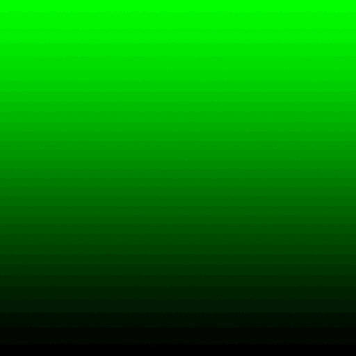
I want to give you an example of these formats with a “worst case” scenario – a fully saturated color (I chose green) gradient.  Here,  you can clearly see the banding in effect.  Then, I will show you a real texture – the Ford Flex – in the various formats.

First – lets look at a 32 / 24 bit example  – ARGB8888 – here we have 256 shades of green.

Green Gradient – ARGB8888

Now – lets take a look at RGB565 – here we have 64 shades of green and we can clearly see some banding. Remember – green has an extra bit for the other primary colors (red and blue) you lose half your colors – down to 32.

Green Gradient – RGB565

Here is RGB555 – 32 shades of green and wow…banding is pretty obvious. This is a common color format in embedded graphics systems.

Green Gradient – RGB555

Here is RGB444 – 16 shades of green…and well…it isn’t pretty.

Green Gradient – RGB444

OK…so this is an example of “worst case” scenarios. A saturated color gradient…but it is instructive to see. Now…I want to digress another moment and talk about 8-bit color.

8-bit “indexed” color and palettes

Wouldn’t it be nifty if we could store bitmaps using only a SINGLE byte?  If we could do this, a 512×512 texture would only be 256KBytes instead of 512KBytes for 16-bit color formats (RGB565/RGB555/RGB444) or 1MByte for 24/32-bit color.

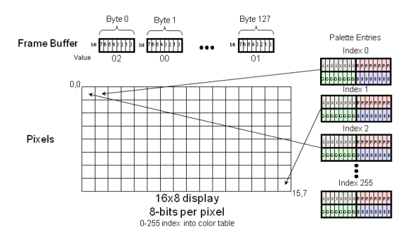
Some graphics controllers DO allow you to use a single byte for a frame buffer / texture / bitmap – whatever.  This is called “indexed color” and it is like a “box of crayons”. Imagine a box of crayons (256 of them in fact) and every crayon is assigned a unique number from 0 to 255. Each crayon can be any color you want it to be – without color depth limitations (OK…it is usually RGB888). In this case, you can create high quality images using a small amount of memory. Take a look at the following example:

8-bit – “Indexed” color

When a value between 0 – 255 is written into the graphics controller’s memory, the graphics controller will go to a table called a “palette” and will index into that table and pull out the RGB value for that particular pixel. Clever, huh?

So…what does a green gradient look like with 256 colors? It looks JUST like its RGB888 counterpart because you can have 256 shades of green in an 8-bit color palette.  For more on indexed / palette color click here.

Back to our regularly scheduled programming

OK, so let’s look at our Ford Flex bitmap in the various color depths.

Here is full 24-bit / 32-bit color:

Ford Flex RGB888

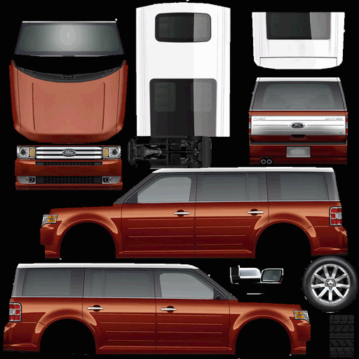
Here it is in 16-bit color – RBB 565 format. You can see some image deterioration, but the image quality is quite acceptable given the fact that you knocked the memory size for the texture in HALF!!!

Ford Flex Texture RGB565

Here is the Ford Flex texture in RGB444 format. Now you can start to see some serious deterioration of image quality.

Ford Flex Texture RGB444

OK…and finally, here is an 8-bit version – which is indexed color / palette driven. You can see again, that this is quite acceptable and given the massive savings in memory and if you have a talented graphics artist around -or you are handy with PhotoShop – then you can probably “tweak” this image to make it work well. The savings in memory for this texture is 75% so it is certainly worth the effort if your graphics controller supports 8-bit textures.

Ford Flex Texture – 8-bit “Indexed” color

Dithering – a neat trick!

A neat trick that we often use when using 16-bit and even 8-bit color is “dithering”. Dithering – according to a nice wikipedia definition – is:

“…an intentionally applied form of noise used to randomize quantization error, preventing large-scale patterns such as color banding in images”

Click here to jump to the full wiki page on dithering.

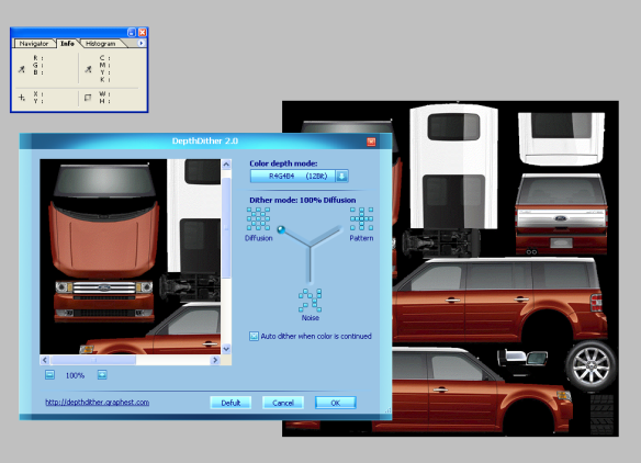
So…how do you dither a 16-bit or 8-bit image?  One nifty way is a free PhotoShop plugin called “Depth Dither” from Graphest.  Graphest seems to be gone…but the plugin is still floating about in places like cnet and can be downloaded from here. Here is depth dither in action in PhotoShop:

Depth Dither in Action

Here is the result when we apply Depth Dither to the RGB444 Ford Flex texture. Compare this to the RGB444 image above. Pretty amazing…right?

Ford Flex Texture RGB444 dithered

Another way to apply “dither” to 16-bit and 8-bit images is to simply go into PhotoShop -or- Gimp and apply 1% or 2% Gaussian “noise” to the image. We have done this many times and it has yielded good results on SOME images.

Once again…back to our regularly scheduled programming

The purpose of all of these “bunny trails” is to form the basis for the 3D model SU3 conversion tool we are developing.  Specifically, what texture formats will we support and what, if any, conversions will we do on the image data?  These are key questions that must be answered.  So, to short circuit the long explanations, we plan to support the following “uncompressed” image formats in Su3De:

  • ARGB8888 – 8 bits each of alpha, red, green and blue. This format is surprisingly not all that common.  Usually, the red and the blue are swapped and this yields:
  • ABGR8888 – same as ARGB8888 except the red and blue values are swapped – this is a pretty common format.
  • BGRA8888 – yes…sometimes the alpha is the last byte and this changes the ordering of the data.
  • BGR888 – 8 bits of red, green and blue, no alpha – 24-bit format – not so common as a “direct” format – will need conversions on certain graphics controllers.
  • RGB888 – same as BGR888 with red and blue swapped
  • BGR565 – 16-bit format – no alpha.
  • RGB565 – 16-bit format – no alpha.
  • BGRX5551 – 16-bit format – no alpha – upper bit unused
  • BGRA4444 – 16-bit format with alpha – 4 bits of each
  • BGRA5551 – 16-bit format with 1 bit of alpha
  • BGRX8888 – 32-bit format with no alpha – essentially 24-bit color packed into 32-bits – upper 8 bits unused
  • I8 – 8-bit indexed color – palette entry must be supplied

Other formats might be added / supported as needed to round out color depth formats.

The methodology for conversion will be loading a PNG, JPG, GIF, whatever into the SU3 model conversion tool along with the .OBJ file – usually this will be automatically supplied in the corresponding .MTL file, then you will select the color depth for the texture based on a drop down list – and then voila…the SU3 will contain your model and texture in the desired format.

In the NEXT entry, I will show what the chunk header and chunk should look like for a texture and we will also cover COMPRESSED textures.  Texture compression is another very interesting topic and refers to the ability of the graphics controller to handle texture decompression in a hardware unit -rather than being handled by the processor directly – which would really defeat the purpose because then we could just use PNGs or JPGs directly…so something to look forward to.

One more thing

I wanted to give an example of the kind of 3D that Su3De will be doing on an actual embedded device…so here is a reference board with THREE LCDs running a demo that we developed using a basic graphics library with 3D primitives.  This is the Jade MB86R01 graphics controller driving the three displays.  This is EXACTLY the sort of thing Su3De is for.  Enjoy:

Super Easy to Use 3D Engine (Su3De) – Binary File Format Part 4 – Texture Maps

NOTE: There were a few minor errors in a couple of the previous posts.  I just wasn’t consistent in explaining the polygonal mesh with regards to vertices.  I have updated the posts and corrected the errors.  The problems were in the area of describing the vertices per triangle relationship.  So, to recap, there are three vertices per triangle and each vertex is comprised of an x, y and z coordinate.  Each coordinate is comprised of a float which requires four bytes.  So, each triangle of the polygonal mesh requires 36 bytes to describe.

Onward…

OK…finally we get to texture maps in the Su3De binary file format.  Texture maps are fairly straightforward to implement, however, there are lots of details that we have to deal with.  In no real order these details include:

  • Texture map color depth
  • Texture map compression
  • Multi-texturing
  • Texture animation
  • Live video as a texture map
  • Recorded or rendered video as a texture map
  • Texture map dimensions
  • Procedural textures

Something I want to also discuss is “terminology”…it can get muddy sometimes so I want to define the terms the way I want to use them with regards to Su3De.  This might result in a street fight…but that’s OK…I fight dirty.

Street fight over 3D terminology

A “texture map” refers to the coordinates (really just relative offsets into the texture bitmap itself) used to map the texture onto the 3D model’s polygonal mesh.

The term “texture” refers to the actual bitmap bits that are being mapped.

UV coordinates” are the values stored in the texture map (one for each vertex of each triangle and corresponding to each triangle) that are the relative offsets into the texture – normalized as values between 0 and 1.  We use the “U and V” to differentiate from X, Y, and Z that are used for mesh coordinates.

I have written a couple of articles / tech papers that you might find interesting if you are new to 3D and texture mapping.  They can be found here:

// Begin Soapbox

Now…at this point, I am going to climb up on my soap box and say a few things. Some of you have been kind enough to express your opinion with regards to the feature set of Su3De.  I want to remind you of the fact that this is to be a “SUPER EASY TO USE 3D ENGINE”.  This means that, at least in the first versions, there aren’t going to be a lot of powerful fancy features.  Yes, I know many of you are very smart…you have told me so…and that in order to be useful Su3De needs this feature or that.  Let’s get something straight…initially Su3De is being developed to satisfy a specific need that I have for a small feature set in a compact UI environment…nothing more.  I am making it “open source” so that you can freely add the features that you want and hopefully many of these new features will find their way into an official Su3De release in the future.  Yes, I know about shaders.  I know about bump / normal mapping.  I know about object physics, collision detection and reflection mapping and yes I know about open source 3D engines like Irrlicht and Ogre (they are awesome).  I appreciate the comments and PLEASE keep them coming…but bear in mind that the goal is a simple product and the feature set is going to be an extremely small subset of overall 3D functionality to achieve a specific goal.  BTW I REALLY liked the suggestion of converting FreeType text into a 3D object that can be used by Su3De…either statically using some tool -or- doing it at run time “on the fly”.  The “on the fly” method might add weight to Su3De that we don’t have the luxury of, however, this could be a compile option.

//End Soapbox

SU3 File format

Putting the texture map and the textures in the actual 3D model binary format along with the polygonal mesh has been a difficult decision.  Does it really belong there?  What about all the things outlined above – texture animation, live streaming video, recorded rendered video, various formats, etc.?  There are lots of good reasons to make the texture map and textures separate files instead of trying to cram everything into a single binary or a single “entity”.  With all this said, I really want a single file (analogous to a PNG as explained before) that contains the entire 3D object.  The “chunk” architecture of the .SU3 file format easily allows us to reference external files should we choose to implement some “advanced” features at a later time. So the decision is that we will have a texture map and a texture in the SU3 file format along with the mesh data (and other required chunks).

Texture Map

Ok, so remember our friend the cube?  Our cube has six sides and twelve faces because each side is made up of two triangles. This makes for thirty six vertices.  As a reminder the vertices look like this:

#pragma pack(1)
/* structure of floating point xyz coordinates */
typedef struct{
    float x;
    float y;
    float z;
}SU3_VTX3F;

static SU3_VTX3F FlexVerts[] = {
 {-10.000000f, 0.000000f, 10.000000f},  //triangle 1
 {-10.000000f, 0.000000f, -10.000000f},  //triangle 1
 {10.000000f, 0.000000f, -10.000000f}, //triangle 1
 {10.000000f, 0.000000f, -10.000000f}, //triangle 2
 {10.000000f, 0.000000f, 10.000000f},  //triangle 2
 {-10.000000f, 0.000000f, 10.000000f},  //triangle 2
 {-10.000000f, 20.000000f, 10.000000f},  //triangle 3
 {10.000000f, 20.000000f, 10.000000f}, //triangle 3
 {10.000000f, 20.000000f, -10.000000f}, //triangle 3
 {10.000000f, 20.000000f, -10.000000f}, //triangle 4
 {-10.000000f, 20.000000f, -10.000000f},  //triangle 4
 {-10.000000f, 20.000000f, 10.000000f},  //triangle 4
 {-10.000000f, 0.000000f, 10.000000f}, //triangle 5
 {10.000000f, 0.000000f, 10.000000f},  //triangle 5
 {10.000000f, 20.000000f, 10.000000f},  //triangle 5
 {10.000000f, 20.000000f, 10.000000f}, //triangle 6
 {-10.000000f, 20.000000f, 10.000000f},  //triangle 6
 {-10.000000f, 0.000000f, 10.000000f},  //triangle 6
 {10.000000f, 0.000000f, 10.000000f},  //triangle 7
 {10.000000f, 0.000000f, -10.000000f},  //triangle 7
 {10.000000f, 20.000000f, -10.000000f}, //triangle 7
 {10.000000f, 20.000000f, -10.000000f}, //triangle 8
 {10.000000f, 20.000000f, 10.000000f},  //triangle 8
 {10.000000f, 0.000000f, 10.000000f},  //triangle 8
 {10.000000f, 0.000000f, -10.000000f},  //triangle 9
 {-10.000000f, 0.000000f, -10.000000f}, //triangle 9
 {-10.000000f, 20.000000f, -10.000000f}, //triangle 9
 {-10.000000f, 20.000000f, -10.000000f}, //triangle 10
 {10.000000f, 20.000000f, -10.000000f},  //triangle 10
 {10.000000f, 0.000000f, -10.000000f},  //triangle 10
 {-10.000000f, 0.000000f, -10.000000f}, //triangle 11
 {-10.000000f, 0.000000f, 10.000000f},  //triangle 11
 {-10.000000f, 20.000000f, 10.000000f},  //triangle 11
 {-10.000000f, 20.000000f, 10.000000f}, //triangle 12
 {-10.000000f, 20.000000f, -10.000000f},  //triangle 12
 {-10.000000f, 0.000000f, -10.000000f},  //triangle 12
};
#pragma pack()

The wire mesh for the cube looks like the image below:

Cube with 36 vertices

As you can see, and as you know from previous posts, there are three vertices per triangle, so our texture map is also going to have three entries per triangle with each entry representing a UV texture map offset. Below is the code that describes the texture map for the cube.

#pragma pack(1)
static SU3_TEX2F FlexTexMap[36] = {
 {0.001200f, 0.665600f}, //triangle 1
 {0.001200f, 0.335200f}, //triangle 1
 {0.331900f, 0.335200f}, //triangle 1
 {0.331900f, 0.335200f}, //triangle 2
 {0.331900f, 0.665600f}, //triangle 2
 {0.001200f, 0.665600f}, //triangle 2
 {0.664100f, 0.333200f}, //triangle 3
 {0.333700f, 0.333200f}, //triangle 3
 {0.333700f, 0.000800f}, //triangle 3
 {0.333700f, 0.000800f}, //triangle 4
 {0.664100f, 0.000800f}, //triangle 4
 {0.664100f, 0.333200f}, //triangle 4
 {0.999300f, 0.333400f}, //triangle 5
 {0.665300f, 0.333400f}, //triangle 5
 {0.665300f, 0.000800f}, //triangle 5
 {0.665300f, 0.000800f}, //triangle 6
 {0.999300f, 0.000800f}, //triangle 6
 {0.999300f, 0.333400f}, //triangle 6
 {1.000000f, 0.666000f}, //triangle 7
 {0.665600f, 0.666000f}, //triangle 7
 {0.665600f, 0.334200f}, //triangle 7
 {0.665600f, 0.334200f}, //triangle 8
 {1.000000f, 0.334200f}, //triangle 8
 {1.000000f, 0.666000f}, //triangle 8
 {0.663000f, 0.665300f}, //triangle 9
 {0.334800f, 0.665300f}, //triangle 9
 {0.334800f, 0.333800f}, //triangle 9
 {0.334800f, 0.333800f}, //triangle 10
 {0.663000f, 0.333800f}, //triangle 10
 {0.663000f, 0.665300f}, //triangle 10
 {0.331900f, 0.332100f}, //triangle 11
 {0.000400f, 0.332100f}, //triangle 11
 {0.000400f, 0.002000f}, //triangle 11
 {0.000400f, 0.002000f}, //triangle 12
 {0.331900f, 0.002000f}, //triangle 12
 {0.331900f, 0.332100f}, //triangle 12
};
#pragma pack()

The actual texture map for the cube we are describing here looks like the following:


No, there isn’t a problem with the bitmap. The top 1/3 is simply not going to be used. Our cube has six sides, therefore we are going to only use the bottom 2/3rds of our texture map area. The benefit of using a cube is that it is very easy to see each “side”.

With a more complex model, the triangle mapping obviously isn’t so straightforward. Speaking of triangle mapping, here is the same texture with the triangle mapping visually applied. This allows you to clearly see all twelve triangles and how they map to the texture.  OK, so the next thing we have to address is how we are going to add the texture map into the .SU3 binary format.

SU3 – Texture Map Chunk

The texture map chunk is defined simply with the chunk length as the number of bytes required to describe the UV coordinates and the chunk type defined as “MTXM”.  To add the texture map to a SU3 file from part 3’s example, we add the following code:

#define FOURCC_MTXM MAKEFOURCC('M','T','X','M')
#pragma pack(1)
typedef struct{
    float u;
    float v;
}SU3_TEX2F;
static SU3_TEX2F FlexTexMap[36] = {
 {0.001200f, 0.665600f}, //triangle 1
 {0.001200f, 0.335200f}, //triangle 1
 {0.331900f, 0.335200f}, //triangle 1
 {0.331900f, 0.335200f}, //triangle 2
 {0.331900f, 0.665600f}, //triangle 2
 {0.001200f, 0.665600f}, //triangle 2
 {0.664100f, 0.333200f}, //triangle 3
 {0.333700f, 0.333200f}, //triangle 3
 {0.333700f, 0.000800f}, //triangle 3
 {0.333700f, 0.000800f}, //triangle 4
 {0.664100f, 0.000800f}, //triangle 4
 {0.664100f, 0.333200f}, //triangle 4
 {0.999300f, 0.333400f}, //triangle 5
 {0.665300f, 0.333400f}, //triangle 5
 {0.665300f, 0.000800f}, //triangle 5
 {0.665300f, 0.000800f}, //triangle 6
 {0.999300f, 0.000800f}, //triangle 6
 {0.999300f, 0.333400f}, //triangle 6
 {1.000000f, 0.666000f}, //triangle 7
 {0.665600f, 0.666000f}, //triangle 7
 {0.665600f, 0.334200f}, //triangle 7
 {0.665600f, 0.334200f}, //triangle 8
 {1.000000f, 0.334200f}, //triangle 8
 {1.000000f, 0.666000f}, //triangle 8
 {0.663000f, 0.665300f}, //triangle 9
 {0.334800f, 0.665300f}, //triangle 9
 {0.334800f, 0.333800f}, //triangle 9
 {0.334800f, 0.333800f}, //triangle 10
 {0.663000f, 0.333800f}, //triangle 10
 {0.663000f, 0.665300f}, //triangle 10
 {0.331900f, 0.332100f}, //triangle 11
 {0.000400f, 0.332100f}, //triangle 11
 {0.000400f, 0.002000f}, //triangle 11
 {0.000400f, 0.002000f}, //triangle 12
 {0.331900f, 0.002000f}, //triangle 12
 {0.331900f, 0.332100f}, //triangle 12
};

#pragma pack()

    //build and write the texture map chunk
    chk.chunkLength = sizeof(FlexTexMap);
    chk.chunkType = FOURCC_MTXM;
    fwrite(&chk, sizeof(SU3_CHUNK), 1, fp);
    fwrite(&FlexTexMap, sizeof(FlexTexMap), 1, fp);
    crc = 0x12345678; //bogus placeholder value
    fwrite(&crc, sizeof(crc), 1, fp);

After the texture is applied to the polygonal mesh we end up with the following rendered image:

Now…of course we haven’t yet written the actual texture data into the SU3 file, we have only written the texture map.  The texture itself is another complex topic and we will address that in the next post.

Housekeeping

So its time for a little bit of housekeeping for the project.  I have secured the domain name of Su3De.org for the project.  Su3De.org will be the official project page. For the source code we will be using GitHub for this project. The GitHub project site is: https://github.com/ricktewell/Su3De.

There is already quite a bit more code developed for this project then I have written about in the blogs.  It is likely that the GitHub repository will stay far ahead of the blog so if you want to “jump forward” a bit – then GitHub will be the place to go.  For example, the 3D OBJ to SU3 converter is starting to work at this point and I will be adding this source to GitHub soon.

So that’s it for now…see you in Su3De.

Super Easy to Use 3D Engine (Su3De) – Binary File Format Part 3 – File Format

In part 2, we talked about vertices in the Su3De binary model format. In this post I want to talk about the “overall” structure of the binary file and then add texture coords and texture maps to the format…in the NEXT post.  I know I said we would talk about textures here, but I got ahead of myself (hard hat area – be flexible and watch out for falling ideas).  We still need to talk a little more about the basic binary format first.  Jumping right in, the Portable Network Graphics (PNG) file format is an exceptionally well thought out binary format and was designed primarily with “network transmission” in mind and as a result has quite a few features geared to that. The PNG format is also equally well suited to being stored on a file system. You can probably tell by now where I am going with all of this talk about PNG. The plan is to use the PNG file format as a basic blueprint for the Su3De binary model format. You can learn more about the PNG format here. If you are knowledgeable in the ways of the PNG, the following will be eerily familiar to you.

Su3De File Header

In all good binary file formats, there should be a few bytes in the beginning that tell you that what you think you are reading is indeed actually what you are reading. For PNGs, this sequence is “0x89, 0x50, 0x4E, 0x47, 0x0D, 0x0A, 0x1A, 0x0A”. These 8 bytes tell you convincingly that you are dealing with a PNG file. Take a look at the hex file dump below of a very small PNG file.

PNG File Hex View

PNG File Header Table

Bytes Purpose
0x89 The high bit is set which is useful to identify a network transmission environment that supports 7-bit instead of 8-bit characters.  In this case, you would see a 0x09 and know that the rest of the file is bogus.
0x50, 0x4E, 0x47 The three ASCII characters representing the characters “PNG”.
0x0D, 0x0A ASCII “Carriage Return” (0x0D) and a “Line Feed”  (0x0A)
0x1A ASCII “Substitute” character which also happens to be a DOS text file “end of file” character
0x0A Another ASCII “Line Feed” (0x0A) perhaps for Unix / Linux text file environments?

A good bit of thought went into this sequence to insure that network transmission systems don’t fiddle with the data as it is transmitted and received.  For example, some file transfer systems change the 0x0D(Carriage Return), 0x0A(Line Feed) into just a Line Feed for example – stripping out the Carriage Return.  Some file transfer systems might ADD a Carriage Return to to the header ending Line Feed… At any rate, if you read the first 8 bytes and you get (in hexadecimal): 89 50 4E 47 0D 0A 1A 0A– then you can pretty much guarantee that the file isn’t being “tinkered with” – especially across a network.

So, what should the Su3De file header look like?  Should it copy the PNG format above or should it “be its own thing?”  I am highly inclined to go ahead and use the PNG file header format and simply replace the ASCII “PNG” with ASCII “SU3”. Why? The reason is simple…I intend to use many of the other elements of a PNG file as well moving forward…so this will make writing a SU3 “reader” simpler because you can use existing PNG reader code to read the SU3 files as well.

The Su3De file header will be:

0x89 – 0x53 – 0x55 – 0x33 – 0x0D – 0x0A – 0x1A – 0x0A

That was easy…wasn’t it?

Chunks of Data Goodness

Now, we are going to talk a bit about “chunks”. Chunks are “groups” of data that fall into a predefined category and are, for the most part, self contained “entities”. Chunks consist of a chunk header usually followed by a data field and ending with a CRC-32 value to insure that the chunk was read correctly (i.e. not corrupted in some way).  So the basic format of a PNG chunk (and now SU3 chunks) looks like the following:

typedef struct{
unsigned int chunkLength;
unsigned int chunkType;
unsigned char chunkData[];
unsigned int chunkCRC;
}CHUNK;

chunkLength is a unsigned 32 bit value telling you how many bytes are in the chunkData field. A length of 0 means that there is no chunkData which is considered valid for some chunkTypes.

chunkType is a four character ASCII code.  The values can be any upper or lower case ASCII letter value – A-Z or a-z or any upper / lower case combination…although in some cases specific upper and lower case characters are meaningful – I will explain later.

chunkData is obviously the data that is meaningful relative to the chunkType. If chunkLength is 0, then there is no chunkData in the chunk.

chunkCRC is a CRC-32 value that protects the chunkType and chunkData fields.  This value is used to determine whether the chunk data that was read is valid or corrupted.  The CRC algorithm used (according to the “official” PNG specification) is defined by ISO 3309 and ITU-T V.42. Sample source code to generate this CRC value can be found here – among many other places I am sure.  It will, of course, be part of the Su3De engine.

NOTE: In PNGs, multi-byte sequences (shorts, ints, floats, etc.) are in big endian format.  In SU3 files, and as we discussed in a previous post, we will “stick to our guns” and use little endian for multi-byte sequences.

The great thing about this chunk architecture is that it is easily extensible.  You can add new chunks to the file format as needed without affecting previous readers / parsers.  If a reader doesn’t know about a particular chunk, it just ignores it.  As long as the “basic” required chunks are present…the model can be used. It is plain to see that you could easily add all kinds of features in the future without breaking the first binary format implementations.

Su3De Chunks

At this point, we are going to switch away from talking about PNG and start talking about Su3De’s binary model format SU3.  The chunk formats will be based on PNG and more about the actual PNG format (especially “chunking” can be found here and here.

Model Header Chunk

The first chunk that must be located in the SU3 is the header chunk identified as “MHDR“.  It is the first chunk in the file and will contain basic information about the model. It is a required chunk. In its initial defined form, it looks like this (subject to change – you are wearing your hardhat right?):

typedef struct{
unsigned int chunkLength;
unsigned int chunkType;
unsigned int faceCount;
unsgined int modelHints;
unsigned byte textureFormat;
unsigned byte vertexFormat;
unsigned int chunkCRC;
}SU3_MHDR;

faceCount represents the number of faces in the model. Each face is comprised of three vertices with each vertex having a x, y and z coordinate. The vertices are defined in the MVTX chunk.

modelHints is a 32-bit bitfield that contains “hints” about the chunks that are in the SU3 model file.  This provides a kind of “heads up” to the model reader about the nature of the model.

textureFormat is a single byte value that indicates what format the texture data (if there is any) is in.  For example, the texture data could be 8-bit palettized, 16-bit direct color (555 or 565), 24-bit direct color, 32-bit direct color with alpha, some compressed data format, etc.

vertexFormat is a single byte value that indicates what format the vertex information is in.  Currently two formats are supported, floating point and fixed point.

Model Vertices Chunk

You read about this “chunk” in the last post, however, we weren’t calling them chunks then.  This chunk is identified as “MVTX” and is also a required chunk. By way of a refresher, here is the chunk format:

typedef struct{
float x;
float y;
float z;
}SU3_VTX3F;

typedef struct{
unsigned int chunkLength;
unsigned int chunkType;
SU3_VTX3F su3Vertices[3]; //x, y, z
unsigned int chunkCRC;
}SU3_MVTX;

su3Vertices represent the polygonal mesh of the model.  Each entry in the SU3_VTX3 array represents a single vertex of a triangle.  The vertex entries are in x, y, z order so su3Vertices[0] would be the x entry of the first vertex of the first triangle, su3Vertices[1] would be the y entry of the first vertex of the first triangle, su3Vertices[2] would be the z entry of the first vertex of the first triangle, su3Vertices[3] would be the x entry of the second vertex of the first triangle…and so on.  It takes nine su3Vertices entries to fully describe one triangle.

Putting it all together “so far”…

Ok, so let’s use a basic 3D cube as an example.  Let’s build a SU3 file and look at it step by step.

First, we will have the file header:
0x89 – 0x53 – 0x55 – 0x33 – 0x0D – 0x0A – 0x1A – 0x0A

Next, we will have a MHDR chunk that will contain some key information:

SU3_MHDR su3mhdr;

su3mhdr.chunkLength = 10; //number of bytes in the data field
su3mhdr.chunkType = 0x5244484D; //ascii MHDR
su3mhdr.faceCount = 12; //a cube will have two triangles per side - and six sides
su3mhdr.modelHints = 0x0001; //bit 0 = mesh present (which is required)
su3mhdr.textureFormat = 0x0; //0 indicates no texture
su3mhdr.vertexFormat = 0x01; //1 indicates floating point format
su3mhdr.chunkCRC = crcval;  //calculated CRC value for type + data fields

After the MHDR chunk, we will have our vertex data in the form of a MVTX chunk:

SU3_VERTICES su3verts;
su3verts.chunkLength = numTriangles * (3 * 12); //3 verts per tri and (3 entries per vert (xyz) * 4 bytes per float
su3mhdr.chunkType = 0x5854564D; //ascii MVTX
//triangle 1
su3verts.vertices[0] = -10f;    //tri 1 vertex 1 x
su3verts.vertices[1] = 0.0f;    //tri 1 vertex 1 y
su3verts.vertices[2] = 10.0f;   //tri 1 vertex 1 z

su3verts.vertices[3] = -10f;    //tri 1 vertex 2 x
su3verts.vertices[4] = 0.0f;    //tr1 1 vertex 2 y
su3verts.vertices[5] = -10.0f;  //tri 1 vertex 2 z

su3verts.vertices[6] = 10f;     //tri 1 vertex 3 x
su3verts.vertices[7] = 0.0f;    //tri 1 vertex 3 y
su3verts.vertices[8] = -10.0f;  //tri 1 vertex 3 z

//triangle 2
su3verts.vertices[9] = 10f;     //tri 2 vertex 1 x
su3verts.vertices[10] = 0.0f;   //tri 2 vertex 1 y
su3verts.vertices[11] = -10.0f; //tri 2 vertex 1 z

su3verts.vertices[12] = 10f;     //tri 2 vertex 2 x
su3verts.vertices[13] = 0.0f;    //tri 2 vertex 2 y
su3verts.vertices[14] = 10.0f;   //tri 2 vertex 2 z

su3verts.vertices[15] = -10.0f;	//tri 2 vertex 3 x
su3verts.vertices[16] = 0.0f;   //tri 2 vertex 3 y
su3verts.vertices[17] = 10.0f;  //tri 2 vertex 3 z

//...and so on for all 12 triangles
su3verts.chunkCRC = crcval; //calculated CRC value for type + data fields

As with the MHDR chunk, a MVTX chunk is required.

The file ends with a chunk appropriately named MEND and it is a mandatory chunk with no data field that signals that “that’s all there is and there isn’t any more.”

typedef struct{
unsigned int chunkLength;
unsigned int chunkType;
unsigned int chunkCRC;
}SU3_MEND;

SU3_MEND su3End;

su3End.chunkLength = 0;
su3End.chunkType = 0x444E454D; //ascii MEND
su3End.chunkCRC = crcval; //calculated CRC value for type + data fields

Quick and Easy Development Environment

I have started using the Bloodshed Dev-C++ development environment for quick code prototyping and testing.  Why…because it is AWESOME that’s why – despite the weird name.  You can find it here.  I use the Dev-C++ 4 version and haven’t tried Version 5 yet.

I wrote a “quick and dirty” SU3 file writer that will write out a 3D cube to a SU3 file using all the chunk stuff we talked about above.  This was done on a Windows XP system…but the code should compile pretty much anywhere. Here is the full source code to that writer:

#include <stdio.h>
#include <stdlib.h>

#define MAKEFOURCC(ch0, ch1, ch2, ch3)  \
    ((unsigned int)(unsigned char)(ch0) | ((unsigned int)(unsigned char)(ch1) << 8) |  \
    ((unsigned int)(unsigned char)(ch2) << 16) | ((unsigned int)(unsigned char)(ch3) << 24 ));

#define FOURCC_MHDR         MAKEFOURCC('M','H','D','R')
#define FOURCC_MVTX         MAKEFOURCC('M','V','T','X')
#define FOURCC_MEND         MAKEFOURCC('M','E','N','D')

#pragma pack(1)
/* structure of floating point xyz coordinates */
typedef struct{
    float x;
    float y;
    float z;
}SU3_VTX3F;

typedef struct{
unsigned int chunkLength;
unsigned int chunkType;
}SU3_CHUNK;

typedef struct{
unsigned int faceCount;
unsigned int modelHints;
unsigned char textureFormat;
unsigned char vertexFormat;
}SU3_MHDR;

//header sequence including 'SU3'
static unsigned char fileHeader[] = {0x89, 0x53, 0x55, 0x33, 0x0D, 0x0A, 0x1A, 0x0A};

static SU3_VTX3F FlexVerts[] = {
 {-10.000000f, 0.000000f, 10.000000f},  //triangle 1
 {-10.000000f, 0.000000f, -10.000000f},  //triangle 1
 {10.000000f, 0.000000f, -10.000000f}, //triangle 1
 {10.000000f, 0.000000f, -10.000000f}, //triangle 2
 {10.000000f, 0.000000f, 10.000000f},  //triangle 2
 {-10.000000f, 0.000000f, 10.000000f},  //triangle 2
 {-10.000000f, 20.000000f, 10.000000f},  //triangle 3
 {10.000000f, 20.000000f, 10.000000f}, //triangle 3
 {10.000000f, 20.000000f, -10.000000f}, //triangle 3
 {10.000000f, 20.000000f, -10.000000f}, //triangle 4
 {-10.000000f, 20.000000f, -10.000000f},  //triangle 4
 {-10.000000f, 20.000000f, 10.000000f},  //triangle 4
 {-10.000000f, 0.000000f, 10.000000f}, //triangle 5
 {10.000000f, 0.000000f, 10.000000f},  //triangle 5
 {10.000000f, 20.000000f, 10.000000f},  //triangle 5
 {10.000000f, 20.000000f, 10.000000f}, //triangle 6
 {-10.000000f, 20.000000f, 10.000000f},  //triangle 6
 {-10.000000f, 0.000000f, 10.000000f},  //triangle 6
 {10.000000f, 0.000000f, 10.000000f},  //triangle 7
 {10.000000f, 0.000000f, -10.000000f},  //triangle 7
 {10.000000f, 20.000000f, -10.000000f}, //triangle 7
 {10.000000f, 20.000000f, -10.000000f}, //triangle 8
 {10.000000f, 20.000000f, 10.000000f},  //triangle 8
 {10.000000f, 0.000000f, 10.000000f},  //triangle 8
 {10.000000f, 0.000000f, -10.000000f},  //triangle 9
 {-10.000000f, 0.000000f, -10.000000f}, //triangle 9
 {-10.000000f, 20.000000f, -10.000000f}, //triangle 9
 {-10.000000f, 20.000000f, -10.000000f}, //triangle 10
 {10.000000f, 20.000000f, -10.000000f},  //triangle 10
 {10.000000f, 0.000000f, -10.000000f},  //triangle 10
 {-10.000000f, 0.000000f, -10.000000f}, //triangle 11
 {-10.000000f, 0.000000f, 10.000000f},  //triangle 11
 {-10.000000f, 20.000000f, 10.000000f},  //triangle 11
 {-10.000000f, 20.000000f, 10.000000f}, //triangle 12
 {-10.000000f, 20.000000f, -10.000000f},  //triangle 12
 {-10.000000f, 0.000000f, -10.000000f},  //triangle 12
};
#pragma pack()

int main(int argc, char *argv[])
{
    char *ptrVerts;
    unsigned int crc;
    SU3_CHUNK chk;
    SU3_MHDR mHDR;

    FILE *fp = NULL;

    fp = fopen("c:\\file.SU3", "wb");

    fwrite(fileHeader, sizeof(fileHeader), 1, fp);

    // build and write the model header chunk
    chk.chunkLength = sizeof(mHDR);
    chk.chunkType = FOURCC_MHDR;
    fwrite(&chk, sizeof(SU3_CHUNK), 1, fp);
    mHDR.faceCount = 12;
    mHDR.modelHints = 0x01;
    mHDR.textureFormat = 0x00;
    mHDR.vertexFormat = 0x01;
    fwrite(&mHDR, sizeof(SU3_MHDR), 1, fp);
    crc = 0x12345678; //bogus placeholder value
    fwrite(&crc, sizeof(crc), 1, fp);

    //build and write the model vertex chunk
    chk.chunkLength = sizeof(FlexVerts);
    chk.chunkType = FOURCC_MVTX;
    fwrite(&chk, sizeof(SU3_CHUNK), 1, fp);
    fwrite(&FlexVerts, sizeof(FlexVerts), 1, fp);
    crc = 0x12345678; //bogus placeholder value
    fwrite(&crc, sizeof(crc), 1, fp);

    //build and write the model end chunk
    chk.chunkLength = 0;
    chk.chunkType = FOURCC_MEND;
    fwrite(&chk, sizeof(SU3_CHUNK), 1, fp);
    crc = 0x12345678; //bogus placeholder value
    fwrite(&crc, sizeof(crc), 1, fp);

    system("PAUSE");
    return EXIT_SUCCESS;
}

Here is a hex dump of the file written by the code above:

SU3 File Hex Dump

If we had an actual reader / renderer (…like the Su3De engine itself), you would see the following:

Rendered Cube – as if from SU3 file

Wrap up for this post

We covered a lot of ground with this post.  In the next one, we will add texture coordinates and texture images to the SU3 format and start working on the .OBJ file converter that will build SU3 files from .OBJ and .MTL files. This will, of course, take several more posts to cover.  I hope you can see where we are going with all of this…and it is starting to make sense.

Thanks for reading and see you in Su3De!  Please add any comments if you think I am off in the weeds somehow and other things you might like to see here…

SUper Easy to Use 3D Engine (Su3De) – Binary File Format Part 2 – Outline

In part 1, I outlined some of the design goals for the Su3De model binary format.  Here, I am going to jump right in and start describing the format based on the work of the past week. The primary idea of the binary format is to be able to pass the object directly on to the Su3De engine so it can be used without any significant conversions or modifications.  This means that the IDEA is for Su3De to pass the model data onto the 3D driver level as intact as possible.  The benefits of this are obvious, speed – with a minor in simplicity. So, what do we need in the file format?  Here is the list I have started with:

  • Vertices
  • Normals
  • Color / Material Data
  • Texture Coords
  • Texture Image
  • Shaders?

Let’s go over these one by one (although vertices will be the focus of THIS post).

Vertices

Vertices are the only truly required objects in the binary format.  The vertices represent the polygonal mesh that makes up the structure of the model.  If all you have is vertices you can draw the 3D object, however, it won’t be very exciting.  It will be end up being flat shaded and will be drawn using a single color.

Ford Flex 3D model flat shaded

The point of all this is that it will be mandatory to have a list of vertices representing the polygonal mesh of the model. The chosen polygon format will be triangles. For now, there won’t be any attempt to “optimize” the mesh – like creating sequences of “triangle strips” or “triangle fans” to reduce the vertex count.  The binary format will be a STRAIGHT UP, three vertices for every triangle kind of thing to start with – meaning there will likely be future versions that will have some optimizations added.

The Ford Flex model shown above, is made up of  1560 triangles (also referred to as “faces”).  This means that there will be x, y, z coordinate entries for each vertex of each triangle. Each x, y, z coordinate entry will be a single precision floating point number requiring 4 bytes.  So each vertex requires 12 bytes and each triangle requires 36 bytes.  So the mesh size will be:

  • 1560 triangles X (12 bytes per vertex X 3 vertices) = 56,160 bytes

The representation of this model in ‘C’ code would look something like this:

static int g_numFlexVerts = 4680;

static SU3_VTX3F FlexVerts[12] = {
 {-7.093400f, 6.617300f, -4.289700f},  //triangle 1 x
 {-6.553800f, 7.036900f, -4.751400f},  //triangle 1 y
 {-7.695800f, 2.596000f, -10.338000f}, //triangle 1 z
 {-7.695800f, 2.596000f, -10.338000f}, //triangle 2 x
 {-8.105300f, 2.607700f, -9.238200f},  //triangle 2 y
 {-7.093400f, 6.617300f, -4.289700f},  //triangle 2 z
 {0.000000f, -3.951100f, 23.106400f},  //triangle 3 x
 {-3.790500f, -3.950100f, 22.999701f}, //triangle 3 y
 {-3.790500f, -4.636200f, 22.999201f}, //triangle 3 z
 {-3.790500f, -4.636200f, 22.999201f}, //triangle 4 x
 {0.000000f, -4.634400f, 23.106400f},  //triangle 4 y
 {0.000000f, -3.951100f, 23.106400f},  //triangle 4 z
//...and so on for the remaining triangles.
};

Now, this is a binary format and one of the decisions we need to make is whether or not the .OBJ file converter will spit out a .H file for the model as an option. I don’t really see the disadvantage in having that as a feature of the Su3De object converter, so we are going to proceed with that as “very likely”. Being a binary format, however, we have to represent this data AS binary information. In this case, the data will look like this in memory:

0x22,0xfd,0xe2,0xc0,0xec,0xc0,0xd3,0x40,0x39,0x45,0x89,0xc0,0xbb,0xb8,0xd1,
0xc0,0x49,0x2e,0xe1,0x40,0x78,0x0b,0x98,0xc0,0xfe,0x43,0xf6,0xc0,0xdd,0x24,
0x26,0x40,0x73,0x68,0x25,0xc1,0xfe,0x43,0xf6,0xc0,0xdd,0x24,0x26,0x40,0x73,
0x68,0x25,0xc1,0x4f,0xaf,0x01,0xc1,0x8f,0xe4,0x26,0x40,0xab,0xcf,0x13,0xc1,
0x22,0xfd,0xe2,0xc0,0xec,0xc0,0xd3,0x40,0x39,0x45,0x89,0xc0,0x00,0x00,0x00,
0x00,0xd3,0xde,0x7c,0xc0,0xe8,0xd9,0xb8,0x41,0x8d,0x97,0x72,0xc0,0x70,0xce,
0x7c,0xc0,0x63,0xff,0xb7,0x41,0x8d,0x97,0x72,0xc0,0xc0,0x5b,0x94,0xc0,0x5d,
0xfe,0xb7,0x41,0x8d,0x97,0x72,0xc0,0xc0,0x5b,0x94,0xc0,0x5d,0xfe,0xb7,0x41,
0x00,0x00,0x00,0x00,0x01,0x4d,0x94,0xc0,0xe8,0xd9,0xb8,0x41,0x00,0x00,0x00,
0x00,0xd3,0xde,0x7c,0xc0,0xe8,0xd9,0xb8,0x41

It is now time to digress and talk about endianness…

Endianness

After some thought, I have decided to simply go with a little endian format for the binary data. For those of you who might not know, endian ordering – which came from Gulliver’s Travels and the people of Lilliput.  Some people would crack their boiled eggs on the big end, while a previous Emperor decreed that you must crack your boiled eggs on the little end.  Therefore, there exists “little endians” and “big endians” in the world of Lilliput.
Endianessmap
Some clever person, decided that they would apply this terminology to the ordering of multi-byte sequences in computer systems.  Say, you have a 32 bit number (which is comprised of four 8 bit bytes…obviously).  How do you order the bytes?  If the number is 0x12345678 (305419896 in decimal) how does it “show up” in memory?  Does it show up as 0x12, 0x34, 0x56, 0x78 (big endian) -or- does it show up as 0x78, 0x56, 0x34, 0x12? It makes a HUGE difference.  There is a whole SLEW of processor systems out there that use big-endian and a whole SLEW of processor systems that use little-endian.  So, we had to make a choice and the choice is little endian for Su3De. For more information from Wikipedia on endianness, click here.

Here is a list of little endian systems – which is quite impressive – (list based on the previously mentioned Wikipedia article on endianness):

  • DragonFlyBSD on x86, and x86-64
  • FreeBSD on x86, x86-64, and Itanium
  • Linux on x86, x86-64, MIPSEL, Alpha, Itanium, S+core, MN103, CRIS, Blackfin, MicroblazeEL, ARM, M32REL, TILE, SH, XtensaEL and UniCore32
  • Mac OS X on x86, x86-64
  • iOS on ARM
  • NetBSD on x86, x86-64, Itanium, etc.
  • OpenBSD on x86, x86-64, Alpha, VAX, Loongson (MIPSEL)
  • OpenVMS on VAX, Alpha and Itanium
  • Solaris on x86, x86-64, PowerPC
  • Tru64 UNIX on Alpha
  • ESX on x86, x86-64
  • Windows on x86, x86-64, Alpha, PowerPC, MIPS and Itanium (and now ARM)

OK…so back to our regularly scheduled programming…

Vertices..again

We have determined that we will need three floats per vertex and three vertices per triangle, so that means that we should be able to just “open” a .SU3 file and start reading out vertices…right?  Well…of course it isn’t THAT simple.  We need a bit more information.  Like how many triangles are in the model.  So organizationally, we are going to need to know that. From a code standpoint then the first thing we read out of the file will be the triangle count (not actually a true statement…but let’s pretend for the moment). This brings us to this:

#pragma pack(1)

typedef struct{
    float x;
    float y;
    float z;
}SU3_VTX3F;

typedef struct{
unsigned int triangleCount;
SU3_VTX3F vertices[1];
}SU3_VERTICES;

#pragma pack()

Wait!!! Is this CODE I am starting to see. Methinks it is!!!

The #pragma pack(1) insures that the compiler will view the structure as being “byte aligned” and won’t add any clever “padding” that might interfere with our interpretation of the data as we read it. If the compiler pads the data, we won’t have any way of knowing this happened and we can easily get misaligned and the model will be read incorrectly.

Ford Flex with vertices showing…

OK…so NOW we have the beginnings, albeit ever so humble, of the Su3De binary file format. At this point, we can create a binary model that has everything we need to draw a 3D model like the Ford Flex example. In the next post, we will discuss the plan to incorporate some other things…starting with texture coordinates and textures.  This will be interesting for sure, so stay tuned.  See you in Su3De again soon.

SUper Easy to Use 3D Engine (Su3De) – Binary File Format Part 1 – Outline

Over the course of the week as I have started work on Su3De, it has become obvious that we are going to need a binary file format for the 3D objects.  In many ways, this file format is at the heart of what Su3De is all about…a simple way to implement 3D graphics in an embedded environment.  The next step was to start investigating the properties of the binary file format and start work on a “converter” that can convert from a common 3D object format to the Su3De binary format, which I will refer to for the time being as the SU3 format.   The overriding rationale for the SU3 format is to create a 3D binary format that is optimized for embedded systems.  There are new 3D graphics engines that are coming that are quite simplified in nature and will be appropriate for simple MCUs (as opposed to the big SoCs found in smart phones and tablet computers – although Su3De will likely find a home here as well).  These new 3D graphics engines (and the older smaller OpenGL ES 1.1 ones) will benefit from Su3De and its simplified binary 3D object format.

Objectives

OK…so what are some of the objectives?  First, we want the format to be efficient for embedded systems.  That means that the format should be appropriate for being:

  1. Read as a file from the file system
  2. “Included” as a .H file into the graphics application’s code
  3. Stored in memory (Flash) at a set location / offset
  4. Beamed in from “outer space” – in other words it could come from anywhere – over a network link, for example

You might be wondering, why create a new file format? SURELY there must be a 3D file format that would be suitable for use without having to create something new.  I was actually hoping the same thing, but the only file format I could find that I thought might be appropriate is the .MOD file format which is a binary version of the Alias/Wavefront .OBJ file format (referred to from now on as simply .OBJ).  The problem is that the .MOD file format is proprietary and mostly undocumented and we aren’t really after a binary representation of the .OBJ file format anyway…but rather an extraction and reorganization of the data inside of the .OBJ file format…so a new file format it will be.

The first consideration was whether or not we should simply do an “on the fly” conversion and allow the Su3De user to just import an .OBJ file directly.  I quickly ruled this out, however, because it didn’t make a whole lot of sense.  Any “up front” conversions you can do to reduce processing makes a lot of sense and having the converter as part of the engine will add some fairly significant overhead.  Additionally, if new 3D formats get supported down the line, the Su3De engine will have to change to accommodate the new format(s).

2 ASCII or not 2 ASCII

Next, why not use an ASCII file format?  This would mean that you could conceivably (if you were a mutant) open a notepad app and type in a 3D object line by line.  Also, the object would be “human readable” and quite portable.  While all of this is certainly true, ASCII is an inefficient way to represent a 3D object inside of an embedded environment.  You immediately have to do all kinds of parsing of the ASCII data and then perform string to int, string to float, sting to ??? conversions and then BUILD the 3D object in memory (which would have to be dynamically allocated…meaning DRAM) for use.  You would lose any benefit of storing a bunch of 3D objects in flash memory and using them directly without doing any conversions.  So ASCII is not in any shape or form ideal for this kind of thing…so a binary file format it will be. I suspect that the data will also be much smaller in binary form than in ASCII form as well (yes, yes, yes you CAN compress ASCII data quite nicely…but then you have to add a decompresser to the Su3De engine and you still have all the ASCII related problems I outlined…so just drop it).

Decisions Decisions

This means that a few decisions have already been made (which is nice).

  1. There will be a converter application that will convert .OBJ files to .SU3 files.  This converter will ideally run on Windows, Linux and Macs.
  2. The  .SU3 file will be a binary format (as opposed to an ASCII format)
  3. The  .SU3 file format will be suitable for file system, direct flash memory storage, and include file use and will be immediately useful to Su3De without any further manipulation or conversions.

The two key pieces of information that the .SU3 file will carry initially are vertex and texture coordinates.  Additionally, triangles will be the preferred geometric mesh format – ideally suited for most OpenGL or basic 3D environments.  Each triangle in the 3D model will have three vertex coordinates and three texture coordinates.  For “shaded” 3D models, the texture coordinates will be absent and some kind of color information will be required – unless we pick some solid color to represent the 3D object as a “fallback” if the only data in the .SU3 file is geometry data.  This will be decided later.  Obviously, the .SU3 format will be “expandable” in some manner so we can add things like material information and normals as needed.  Since the “winding order” will be correct in the .OBJ file to begin with, when we create the vertex and texture coordinate lists for each triangle…the winding order will stay correct (kind of obvious isn’t it…but still worth stating…)

OK…so no actual code THIS post, but we are getting there. The next entry will discuss the .SU3 format in a little more concrete detail and will highlight some of the technical issues that we have run into along the way.  Should make for interesting reading…so stay tuned!

SUper Easy to Use 3D Engine (Su3De) – Project Start

Suede 3D Engine

So, I have a need for a VERY simple to use 3D engine for embedded systems and I have decided, after months of vacillating on the issue, to write one. It will be Open Source and the pieces will be published here as well as Source Forge. The engine will sit on top of three 3D architectures initially. OpenGL ES 1.1, OpenGL ES 2.0 and the Fujitsu V03 graphics access library for the Fujitsu Jade “MB86R01” SoC. It will be developed entirely in ANSI ‘C’ and the goal is to make it abstract enough that it can move to other platforms like Direct3D with ease – but we will see.

First, the name. Every project must have a name. This one is “Su3De” which is an extremely FORCED acronym based on the phrase “Super Easy to Use 3D Engine”. It will, of course, be pronounced “Suede” and I will not use a cow for a logo…although cool cow textures might be sprinkled throughout some of the code samples…just because.  Who wouldn’t love a cow textured tea pot? Don’t judge.

What will make this 3D engine “easy to use”? The API. The plan is to make it as simple as possible. This means a lot of work will be done underneath the API to simplify things. Most of the work will be focused on two main categories.

Loading Objects
Transforming Objects

The plan is to have simple and obvious API calls like Load3DObject(), Rotate3DObject(), Translate3DObject(), Scale3DObject(), etc. Other API functions will be related to things like render contexts and housekeeping.

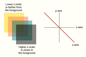
One of the “tricks” in developing Su3De is going to be in compositing 2D and 3D images together to form a scene. The goal is to do this efficiently and determine a way to do it so that you aren’t rendering the entire scene for every frame. I plan to rethink the way 3D engines work and will likely be bucking convention in several key areas – especially in the area of “Z” ordering – which is the “depth” component of the objects that are being rendered.

Initially the 3D object file format that will be supported by Su3De will be .OBJ files. After that, we will see where it goes. I also plan to support 2D file formats starting with .PNG – both for 2D “objects” as well as 3D object textures. 2D objects will be loaded and rendered as two polygons forming a square with the .PNG as the texture map.

There are many features in the Fujitsu V03 graphics access library that I will want to take advantage of, like using live video as a texture and the layering features of the display controller. These features are extremely useful – but aren’t present in the standard OpenGL APIs…so I will have to balance these somehow.

At any rate, welcome aboard. I hope you find the project interesting. Feel free to comment and tell me what you are thinking as I move forward. It is likely that I will barge forward and run straight into a brick wall and have to back up and change course from time to time, so be prepared for that. It should be fun… See you in Su3De! First “coding” post should be next week sometime. I am a big fan of the Processing Environment and will be using it to “prototype” the code and the initial APIs. Please download it and follow along! See you next week!!!!